Форматы блоков
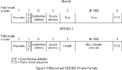
Ethernet and IEEE 802.3 frame formats are shown in Figure 5-2.

Both Ethernet and IEEE 802.3 frames begin with an alternating pattern of ones and zeros called a preamble. The preamble tells receiving stations that a frame is coming.
The byte before the destination address in both an Ethernet and a IEEE 802.3 frame is a start-of-frame (SOF) delimiter. This byte ends with two consecutive one bits, which serve to synchronize the frame reception portions of all stations on the LAN.
Immediately following the preamble in both Ethernet and IEEE 802.3 LANs are the destination and source address fields. Both Ethernet and IEEE 802.3 addresses are 6 bytes long. Addresses are contained in hardware on the Ethernet and IEEE 802.3 interface cards. The first 3 bytes of the addresses are specified by the IEEE on a vendor-dependent basis, while the last 3 bytes are specified by the Ethernet or IEEE 802.3 vendor. The source address is always a unicast (single node) address, while the destination address may be unicast, multicast (group), or broadcast (all nodes).
In Ethernet frames, the 2-byte field following the source address is a type field. This field specifies the upper-layer protocol to receive the data after Ethernet processing is complete.
In IEEE 802.3 frames, the 2-byte field following the source address is a length field, which indicates the number of bytes of data that follow this field and precede the frame check sequence (FCS) field.
Following the type/length field is the actual data contained in the frame. After physical-layer and link-layer processing is complete, this data will eventually be sent to an upper-layer protocol. In the case of Ethernet, the upper-layer protocol is identified in the type field. In the case of IEEE 802.3, the upper-layer protocol must be defined within the data portion of the frame, if at all. If data in the frame is insufficient to fill the frame to its minimum 64-byte size, padding bytes are inserted to ensure at least a 64-byte frame.
After the data field is a 4-byte FCS field containing a cyclic redundancy check (CRC) value. The CRC is created by the sending device and recalculated by the receiving device to check for damage that might have occurred to the frame in transit.
[]
[]
[]
